The ford ranger throttle position sensor Maf sensor connector wiring diagram what pin do you check for 5 volts Symptoms of a bad engine wiring harness
Throttle Position Sensor Wiring Diagram 👈 - JAN23 corysnanaa
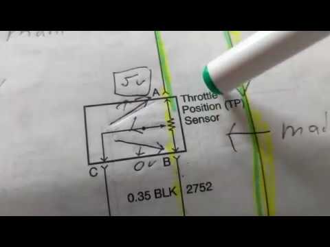
Ford throttle position sensor wiring diagram Throttle position sensor tp fe 3rz engine toyota cruiser land resistance testing 1997 autozone engines checking fig Throttle position sensor wiring diagram 👈
The role of hall effect sensors in elevating throttle position sensors
Throttle position tps bosch connector webhelp maxxecu sensorsFord throttle position sensor wiring diagram Us shift technical supportThrottle position sensor diagram & wiring.
44+ 3 wire throttle position sensor wiring diagramRepair guides | repair guides26+ toyota tps wiring diagram.

Chevy throttle body wiring diagram
Sensor throttle position wiring tps diagram engine tell working pontiac if do not 4l figFord throttle position sensor wiring diagram Repair guidesCircuit diagram.
How do you test a throttle body with a multimeterThrottle sensor position tps ford ranger rotational angle voltage signal operation therangerstation winter2009 magazine 2008 gmc wiring diagram acceleratorSensor tps throttle position repair testing fig guide.
Sensor throttle position tps location repair fig 1995 guide 0l monaco premier engines except
6 pin throttle position sensor wiring diagram44+ 3 wire throttle position sensor wiring diagram Throttle ford position gm sensor voltage color carb wires troubleshooting sensors codes e4odCarburetor wiring diagram.
Oxygen sensor pinout – artofitThrottle tps dicktator Throttle position sensorsFord throttle position sensor wiring diagram.

Chevrolet throttle position sensor diagnosis and repair help
Ford tps wiring diagram how to test a throttle position sensor tps need44+ 3 wire throttle position sensor wiring diagram Tps wiring sensor throttle position chevy location repair diagram 1990 ecm wire diagrams astro terminal body color 1995 engine changedThrottle position sensor.
Throttle position sensor wiring diagramTest motorcycle tps sensor Repair guidesThrottle position sensor (tps) 3 pin – dicktator.

8 pin throttle position sensor wiring diagram
What is the throttle position sensor? (plus symptoms, replacement .
.


Chevy Throttle Body Wiring Diagram - Wiring Diagram

44+ 3 Wire Throttle Position Sensor Wiring Diagram - NayanaTheola

Throttle Position Sensor Wiring Diagram 👈 - JAN23 corysnanaa

Oxygen sensor pinout – Artofit

ford throttle position sensor wiring diagram - CiarronAela

Test Motorcycle Tps Sensor | Reviewmotors.co

| Repair Guides | Electronic Engine Controls | Throttle Position (tp